Refrigerated Trucks and Cold Food Transportation: The commercial food sector, including agriculture, food manufacture transport and retailing is responsible for 22% of the UK’s total greenhouse gas emissions. Food distribution and retail accounts for approximately one third of this, with food transport which includes motive power and refrigeration estimated to be responsible for 1.8 % of total emissions.
Table of Contents
Introduction
Road transport refrigeration equipment are required to operate reliably in much harsher environments than stationary refrigeration equipment. Due to the wide range of operating conditions and constraints imposed by available space and weight, transport refrigeration equipment have lower efficiencies than stationary systems.
This, coupled to rapidly increasing use of refrigerated transport arising from the much wider range of transported goods, home delivery and greater quality expectations, is placing considerable pressures on the food industry to reduce the energy consumption of refrigerated transport.
There are also very limited chill holding tolerance periods where product may be above the minimum but this must be consistent with food safety requirements, for example during transfer from storage depot to transport vehicle.
The transport of perishable food products, other than fruit and vegetables, and the equipment used for the carriage of these products is governed by an agreement drawn by The Inland Transport Committee of the United Nations Economic Committee for Europe in 1970-1971.
The aim is to facilitate international traffic by setting common internationally recognised standards. The agreement is known as the ATP agreement and was adopted in the UK in 1980. It provides common standards for temperature controlled transport vehicles such as road vehicles, railway wagons and sea containers and sets down the tests to be done on such equipment for certification purposes.

The ATP also classifies refrigeration and heating equipment in terms of temperature control at -20 °C, -10 °C, 0 °C and +12 °C. The most common ATP classification for equipment certifies it for all temperature classes. This is identified using the distinguishing mark FRC, which stands for Mechanically Refrigerated and with Heavy Insulation.
The refrigeration equipment installed on a refrigerated vehicle must also possess a valid ATP capacity report.
The agreement states that new refrigeration equipment installed on a refrigerated vehicle must have a heat extraction capability at the class limit temperature of at least 1.35 times the heat transfer through the walls in a 30 °C ambient temperature and 1.75 times if the refrigeration unit was tested separately outside the vehicle to determine its effective cooling capacity at the prescribed temperature.
The ATP certificate ensures that the insulated body and the refrigeration unit have been tested by a third party and that the two have been appropriately matched. An ATP certified vehicle or body could carry a single certificate that covers both the insulated body and the refrigeration unit.
The ATP certificate is valid for six years but can be extended by another three years on condition that an “in service” examination is carried out. There are concerns, however, that in-service testing procedures are not stringent enough and may lead to increased energy consumption.
In the UK the average number of ATP certificates issued in one year is approximately 1500. ATP certified bodies frequently operate in service for 9 to 12 years depending on the type of operational service impacting on the body.
Technologies currently in use in food transport refrigeration Vehicles
The majority of refrigerated road transportation (units = t.km) is conducted with semitrailer insulated rigid boxes. In Europe the typical construction dimensions of a semitrailer rigid box are fixed for the external length and width but the external height and internal dimensions can vary depending on the individual design type. These dimensions are as follows:
External dimensions: 13.56 m in length, 2.6 m in width and 2.75 m in height.
Internal dimensions: 13.35 m, 2.46 m, and 2.5 m.
Many factors are considered in the design of the envelope of a refrigerated transportation unit: extremes of exterior weather conditions, desired interior conditions, insulation properties, infiltration of air and moisture, trade offs between construction cost and operating cots and physical deterioration from shocks and vibrations.
A rigid semi-trailer box normally consists of expanded foam insulation sandwiched between two external skins. Each skin consists of a few millimeters of plywood covered with a glass reinforced polyester, steel or aluminium skin. The most popular insulation is expanded polyurethane (PU) foam with cyclopentane as the blowing agent. This construction achieves a thermal conductivity in the region of 0.022 W/(m K).
In side walls where thickness is constrained by the maximum permissible insulated vehicle width of 2.60 m and europallet dimensions (europallet is 1.0 m deep by 1.20 m wide), this construction can accommodate 2 europallets side by side but insulation thickness is limited. Another popular insulation material is extruded polystyrene.
The thermal conductivity of this insulation is higher than PU foam but in floor and roof construction where there are fewer constraints for overall thickness, body builders can offset thermal losses by using thicker panels. Roofs and floors often have 100 mm or more insulation. In side walls, the constraints mean the insulation is rarely more than 45-50 mm thick.
The performance of insulation materials deteriorates with time due to the inherent foam characteristics. Recent data show a typical loss of insulation value of between 3% and 5% per year which can lead to considerable rises in the thermal conductivity after a few years.
If a 5% yearly ageing is assumed, a vehicle with an initial K-coefficient of 0.4 W/(m2 K) will have a K-coefficient of 0.62 W/(m2 K) after nine years of operation, resulting in a 50 % increase in energy consumption and CO2 emissions.
If one considers the large number of refrigerated vehicles and containers in use worldwide the global impact of the reduction of insulation effectiveness is considerable.
Refrigeration units
The most common refrigeration system in use for refrigerated food transport applications today is the vapour compression system. Mechanical refrigeration with the vapour compression cycle offers a wide range of options for compressor drive methods. The choice may be based on duty required, weight, noise requirements, maintenance requirements, installation cost, environmental considerations and fuel taxation.
The performance and power requirements of these systems are normally assessed at full load. In reality however, transport refrigeration systems operate over a wide range of loads. To match the load the refrigeration system may be switched on and off or its capacity modulated to maintain the set temperature with a consequent reduction in efficiency.
Depending on the system design envelope and the setup expected Coefficient of Performance (COP) is generally between 0.5 and 1.5. The most common drive systems for refrigerated transport vapour compression systems are:
Vehicle alternator unit
With this method which is commonly used in small delivery vans, the vehicle engine crankshaft drives an upgraded single alternator and a 70 Ah battery. The alternator charges the vehicle battery which feeds a small refrigeration system with 12 V dc supply. The system can also be driven with a 230V mains electric supply during standby.
Direct belt drive
With this system, which is used in the majority of van sized vehicles, the compressor of the refrigeration unit is directly driven from the vehicle engine through a belt.
Auxiliary alternator unit
This system uses a dedicated large alternator driven by a belt from the main traction engine, generating power to drive an electric motor in the refrigeration unit. Fan motors for the heat exchangers and the control system are also fed from the alternator output.
An alternative arrangement for an alternator system is to use a diesel generator system. Using the ‘genset’ drive gives the option of using red tax free diesel to power the unit unlike running an alternator from the vehicle.
Auxiliary Diesel Unit
This system uses an engine built into the refrigeration unit which can be powered either by red diesel (cheaper) or white diesel (lower environmental impact). An optional particle filter and catalyst in new engine technologies can clean the exhaust emissions from an engine run on white diesel, leading to over 90% reduction in emissions.
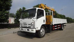
The majority of medium to large vehicles use self-contained refrigeration units which include a self-contained diesel engine. At -20°C and running at full capacity, the fuel consumption of the auxiliary diesel engine driving the compressor can be between 1 and 5 litres per hour depending on the size of the unit.
These units are usually nose-mounted, or less commonly under-slung (below the insulated body). The disadvantage of under-slung units is that the condenser is in a poor location to get clean air.
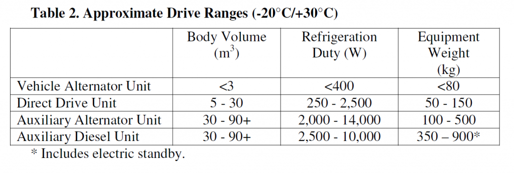
Table 2 lists the most common drive methods and uses general approximated data for refrigeration capacity and weight.
Air Delivery Systems
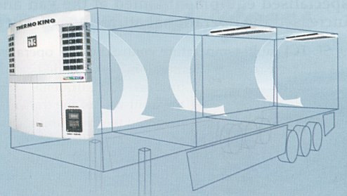
A typical arrangement of the refrigeration system and air distribution in a refrigerated semi-trailer is shown in Figure 1. In these vehicles, top air delivery is predominately used.
Refrigeration unit fans cause temperature-controlled air to circulate around the inside of the vehicle roof, walls, floor, and doors to remove heat which is conducted and infiltrated from the outside, returning to the cooling coil via the floor or space under pallets as shown in Figure 2.
For chilled cargoes horizontal channels are required between rows of cartons to allow good return airflow through the load, Some of the air should also flow through and between the cargo, particularly when carrying fruit and vegetables, where heat of respiration may be a significant proportion of the heat load.
To facilitate air return to the evaporator coil, some trailers are fitted with a false bulkhead wall with metal grill or holes in the lower part for return air passage. The placement of air delivery and return on the same side of the refrigerated box for reasons of compactness and simplicity, makes the achievement of uniform temperature distribution in the cargo difficult.
In recent years considerable effort has been devoted to the optimisation of air flow and temperature distribution in refrigerated cargoes using a variety of modelling techniques including computational fluid dynamics .


Multi-compartment vehicles
In multi-compartment vehicles the refrigerated space is subdivided into a number of compartments with individual temperature set-points to provide logistics flexibility for many business operations. It is common practice for supermarket chains to deliver produce inside multi-compartment semi trailers.
The different temperatures in each compartment are achieved by using distributed evaporator coils fed from a single condensing unit. In general practice the coldest compartment is located at the front and the warmest is at the rear but any temperature configuration is possible. The design and control of refrigeration systems for multi-compartment vehicles is much more challenging than that for single compartment vehicles.
Factors specific to the design of multi-compartment refrigeration systems are the heat transfer between the compartments, product loading patterns and door openings and method of temperature control.
Eutectic systems
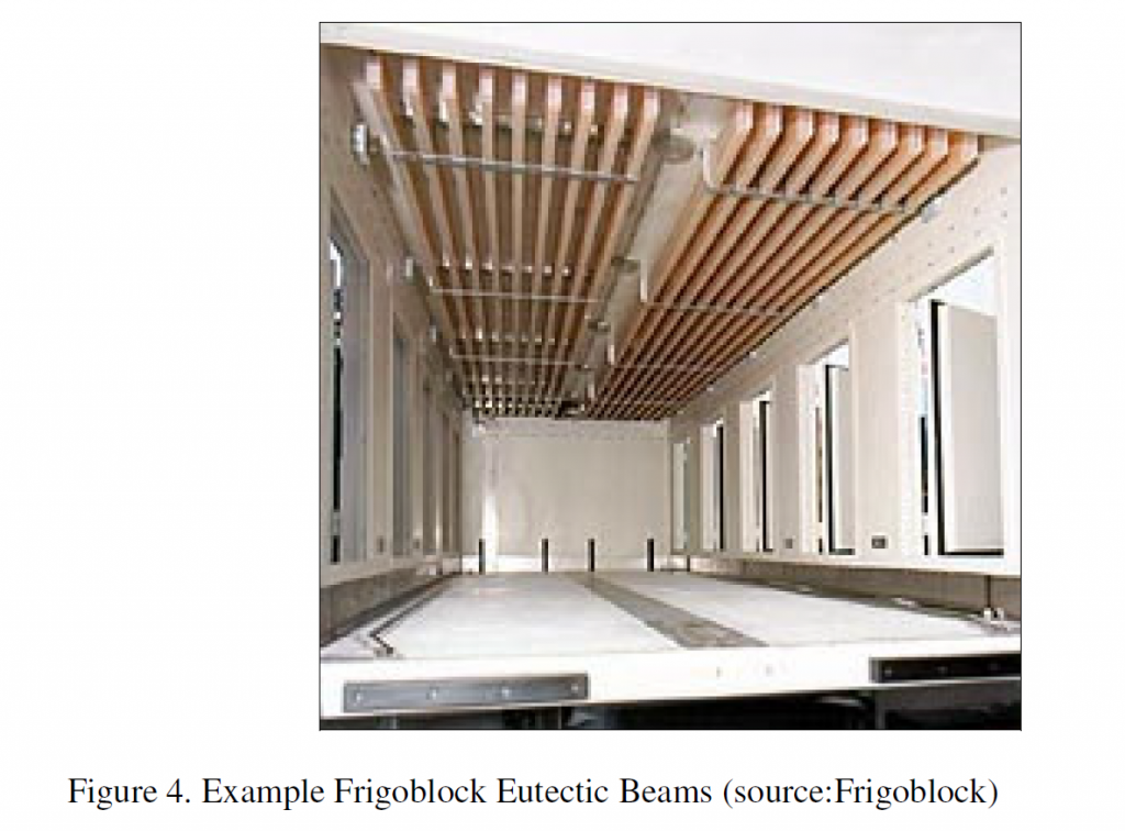
Eutectic systems consist of hollow tubes, beams or plates filled with an eutectic solution (phase change material) to store energy and produce a cooling effect whenever necessary to maintain the correct temperature in the refrigerated container.
The Eutectic concept is different to conventional refrigeration systems in that a cold source (heat absorption) is provided by phase change material rather than direct expansion of refrigerant gas. The plates or beams that contain the eutectic are charged (frozen down) at night on mains power. Once the beams are frozen they operate silently and provide reliable, rapid cooling for a specific duration of time.
Systems for food transport applications can be based solely on eutectic thermal energy storage or can be a combination of eutectic and vapour compression system. Such systems which may be suitable for small deliveries where the heat loss through frequently opening doors can be a major problem.
They can offer savings by using a small refrigeration system running relatively efficiently or if coupled with a mechanical refrigeration device can offer efficiency savings by reducing the number of on/off control cycles.
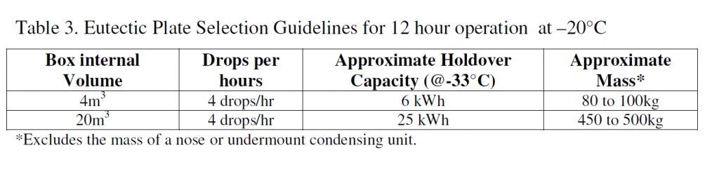
There are fixed sizes of plates or beams available and selection involves calculations based on the prescribed delivery rounds, the journey length, number of door openings, time period etc. table 3 gives an example Eutectic plate selection guidelines.
Some manufacturers have now developed static refrigeration units that are capable of charging eutectic systems when linked up via a connector. This removes the requirement for each refrigerated vehicle to have its own condensing unit and therefore decreases costs.
Cryogenic Cooling Systems
As an alternative to mechanical refrigeration, total loss systems using liquid nitrogen or carbon dioxide injection may be used. Advantages are rapid pull-down of temperature and relative silence. For longer journeys, these systems are expensive to operate; so cryo-mechanical systems exist which combine the rapid pull down of a total loss refrigerant with the more economical steady running of a mechanical system.
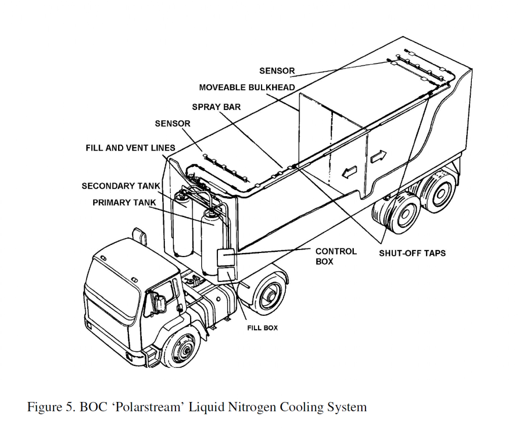
The BOC Polarstream in-transit refrigeration system may be integrated into road vehicles or freight containers. This system is shown schematically in Figure 5. It uses liquid nitrogen in the cooling process, which vaporises as it is released into the container reducing the temperature uniformly.
The liquid nitrogen is stored in tanks connected to a spray bar that runs the length of the vehicle. A pneumatically powered temperature controller responds to sensors located throughout the vehicle to maintain the required temperature.
Energy Consumption for refrigerated road transport
Approximately 650000 refrigerated road vehicles are currently in use within the EU..
These vehicles can be grouped into three main types:
• small converted vans (up to 3.5 tonnes, for example for catering or ice cream distribution),
• rigid vehicles (trucks, up to 32 tonnes) and
• articulated vehicles (up to 44 tonnes), which are used for the majority of refrigerated road transportation operations. Articulated vehicles over 33 tonnes, account for around 80% of the total tonne-km goods movement in the UK.
Table 3 below shows guideline figures for fuel (gas oil) consumption rates of self contained mechanical road refrigeration equipment charged with HFC404a refrigerant. The data is generalised from a number of models of equipment and based on ATP test conditions for maximum continuous output, operating in +30°C ambient.
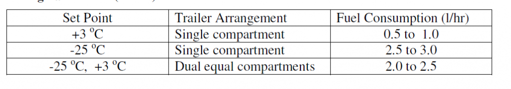
There is less information available for in-field fuel consumption rates where equipment cycles on/off to meet the specific refrigeration duty requirement. Table 5 summarises some data for infield fuel consumption rates for a dual compartment 13.6m semi trailer in 30°C ambient.
Optimal infield fuel consumption is dependent on aspects such as the type of operation, solar load, fuel density, control software setup e.g. continuous modulation or on/off, cycle termination temperatures. The total distance travelled by road freight transport worldwide in 2005 was estimated to be 16,000 mio t.km.
European road freight makes up 1,800 mio t.km and about a third is refrigerated, resulting in approximately 600 mio t.km. The United Kingdom represents about 8% of the European road refrigerated freight. The fuel consumption of various types of vehicles involved in freight transport in the UK and the distance run in 2004 is given in Table 6. This fuel consumption excludes the energy consumed by the refrigeration equipment.
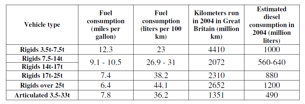
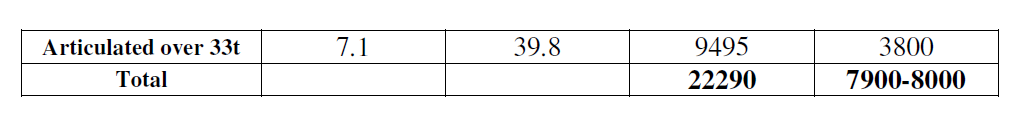
From Table 5 it can be seen that the in-service fuel consumption of a refrigeration unit will be around 2.0 l/hr. If it is assumed that an articulated vehicle will cover 60 km per hour, from Table 6 its fuel consumption can be estimated to be 24 l/hr. This shows that the fuel consumption of the refrigeration unit will be approximately 8% of the total fuel consumption of the refrigerated vehicle.
If one assumes that 1.8% of the total greenhouse gas emissions in the UK is for food transport, and one third of this is refrigerated with the refrigeration systems being responsible of 8% of the energy consumption of the vehicle, then a very rough estimate will be that refrigerated equipment in food transport operations in the UK are responsible for 0.05% of total greenhouse gas emissions.
Possible alternative technologies for transport refrigeration
Diesel engines used to drive transport refrigeration equipment, typically have a thermal efficiency of 40%. Assuming a heating value for diesel of 43.2 MJ/kg and a density of 820 kg/m3, the amount of energy rejected in the form of hot exhaust gases and thermal energy dissipated by the radiator for each litre of fuel that is used is 21.25 MJ/l or, 5.9 kWh/l.
Recovering only a small portion of this “free” wasted energy to operate a thermally driven refrigeration system, would be more than enough to cover the refrigeration requirements of a semi-trailer. In thermally driven refrigeration technologies, absorption and/or adsorption, the conventional mechanical compressor of the common vapour compression cycle is replaced by a ‘thermal compressor’ and a sorbent.
The sorbent can be either solid in the case of adsorption systems or liquid for absorption systems. When the sorbent is heated, it desorbs the refrigerant vapour at the condenser pressure. The vapour is then liquefied in the condenser, flows through an expansion valve and enters the evaporator. When the sorbent is cooled, it reabsorbs vapour and thus maintains low pressure in the evaporator.
The liquefied refrigerant in the evaporator absorbs heat from the refrigerated space and vaporises, producing the cooling effect.
Absorption systems for food transport refrigeration
Koehler et al. designed, built and tested a prototype of a single-stage ammonia/water absorption system for truck refrigeration powered by the exhaust gases of the tractor. A schematic diagram of this prototype is shown in Figure 6. The prototype was tested for interior temperatures between -20°C and 0°C and exterior temperatures in the range 20°C to 30°C.
Test results are shown in Figure 7. With temperatures of the exhaust gases in the range 440°C to 490°C when entering the generator and 180°C when leaving it and an exhaust flow rate of 360 kg/h, cooling capacities in the range 6-10 kW and COPs between 0.23 and 0.3 were obtained.
This capacity is sufficient to satisfy the refrigeration requirements of a typical refrigerated semi-trailer, even when applying a safety factor of 1.75 to the theoretically calculated load.
For a vehicle with an inside temperature Tin of -20°C, an outside temperature Tamb of 30°C, a K-value of 0.4 W/(m2K) and a mean section S=150 m2, the required refrigeration capacity at the indoor temperature of -20°C taking into account a safety factor of 1.75 is 5.25 kW.
Furthermore, according to the investigators, the COP of the single-stage ammonia/water absorption system could have been significantly improved by optimising the cycle. Figure 7 shows some of the performance characteristics of the cycle. Some of the results they obtained are provided by the following graphs:


The authors also analysed through simulation the performance of the system by calculating the effective available energy in the exhaust gases for a range of road conditions. In the analysis the temperature of the gases leaving the generator was assumed to be constant at 200 °C for a range of driving cycles. Several truck engines with power from 250 hp to 420 hp were also analysed to calculate the exhaust mass flow rate.
The results indicated that such a system will be suitable for use in level roads where it will be able to cover more than 80% of the refrigeration needs. For mountain roads and city conditions there will not be enough heat available with the system sometimes generating insufficient cooling and at other times excess cooling.
To address this problem, an auxiliary heat source will be to compensate for the times when the available heat is insufficient. Alternatively a storage device such as eutectic system can be used in conjunction with the absorption system. Similar results have been found by Horuz, who used the exhaust gases of a 6-litre turbo diesel engine to drive a 10 kW commercial aqua-ammonia vapour absorption refrigeration system.
The refrigeration unit was powered successfully up to its rated capacity but a significant reduction of the cooling capacity (down to 1 kW) was observed when the engine was run at low speeds. The effect on the performance of the engine of introducing the generator in the exhaust system was found to be quite low, with a maximum decrease in efficiency of 2 %.
Another issue to be addressed with respect to the use of sorption refrigeration systems is the mounting of the refrigeration system on the articulated vehicle.
Adsorption systems for food transport refrigeration
Christy and Toossi designed, modelled, built and tested a trailer refrigeration and bus air-conditioning ambient-air cooled adsorption system. The design employed four activated carbon sorbent beds and ammonia (R717) as a refrigerant.
The sorption system was then theoretically characterized (size, weight, heat input, operational modes and layout configurations) for the purpose of being capable of maintaining temperatures in the range -18°C to 4.5°C for transport refrigeration.
The diesel engine available heat rates for powers between 225 hp and 525 hp were identified to be in the range 40 kW to 60 kW for the coolant circuit and 40 kW-140 kW for the exhaust gases. The cooling requirements of large refrigerated semi-trailers were considered to be equal to the cooling capacities of the units usually installed on these vehicles, that is to say about 15 kW.
It should be noted that those units are usually 200 to 300 % oversized. Practical COP values used for system design were in the range 0.6 to 1 and specific cooling power rates (measure of the evaporator cooling load per mass of sorbent material) were considered to be around 614 W per kilogram of carbon for ammonia refrigerant and and 198 W per kilogram of carbon for R134A refrigernat.
Following these assumptions, a feasibility analysis of refrigeration systems using either R717 or R134A with cooling capacities of 9 kW, 19 kW and 35 kW (bus airconditioning) was carried out. Another very interesting aspect of the study was the investigation of the layout of such a system to identify the best way of installing it on a conventional articulated vehicle.
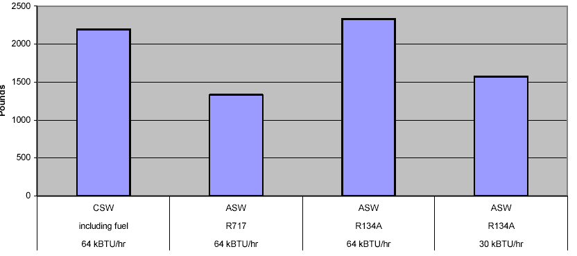
First, the weight of adsorption systems using either R717 or R134A as a refrigerant was estimated for different cooling capacities and compared to a vapour compression. As shown in Figure 7, adsorption systems were found to be potentially lighter than a conventional system when a diesel fuel tank of around 300 kg weight was considered for the conventional system.
The most attractive location for the adsorption system was found to be the tractor, transferring the cooling effect to the trailer with a secondary fluid.
Thermoelectric cooling
Thermoelectric devices can convert electrical energy into a temperature gradient. This effect was discovered by Peltier in 1834 but its use remained marginal till the development of semiconductor materials. It was first used for refrigeration and air conditioning purposes in the 1950s.
Thermoelectric devices are solid-state devices showing several considerable advantages: they are reliable, noise-free, maintenance-free and vibration-free since they do not contain mechanical moving parts, they have been found to have a long life of more than 100000 hr, they are environmentally friendly since they do not need chlorofluorocarbons or any other refrigerant, they are small in size, light in weight, they can allow a very precise temperature control (0.1°C) and they are fully reversible, so they can for example heat a cargo if necessary instead of cooling it to protect it against frost damage.
Nevertheless, they have a major drawback that has prevented them from being used in large scale refrigeration applications such as foodstuff transportation and storage so far: their COP is much lower than that of
conventional mechanically-driven compressor vapour cycle units under the typical conditions required for those applications.
The application of Peltier coolers and their modelling are still an active field of research. Chatterjee and Pandey designed, built and tested thermoelectric cold chain chests with capacities up to 2.5 suitable for storing and/or transporting medical materials at temperatures down to –17 °C.
The COP of these small refrigerators has been found to be in the range 0.12-0.26. Astrain et al. have developed a computational model to simulate thermal and electric performance of thermoelectric refrigerators and have designed and tested a thermoelectric refrigerator to test their model, which has shown very good agreement with test results. COPs between 0.15 and 0.65 were obtained.
Principles of thermoelectric cooling
The thermoelectric cooling effect is produced when a direct current is passed through at least one pair of n and p-type semiconductor materials, usually bismuth telluride Bi2Te3.
When a direct current is circulating through the device, electrons pass from a low energy level in the p-type material to a higher energy level in the n-type material and as a result absorb heat from the environment. The heat is liberated at the other end of the device when the electrons return to a low energy level in the p-type material.

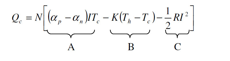
These two sides of the device are called the “cold end” and “hot end” respectively and the corresponding temperatures are identified as Tc and Th. The useful heat absorbed by a thermoelectric cooler at its cold surface (Qc) is composed of three components: the Peltier heat pumping (A), which is reduced by the conduction across the semiconductor elements (B) and the resistive heating within the elements (Joule heat, C). Qc is expressed as follows:
Thermoelectric power generation
When a temperature differential is established between the two sides of the semiconductor material, a voltage is generated. This voltage is directly proportional to the temperature differential and the constant of proportionality is referred to as the Seebeck coefficient.
A thermoelectric device can therefore also convert thermal energy into electric energy: this is the inverse effect of the Peltier effect, called the Seebeck effect, which was discovered in 1821. Like thermoelectric coolers, thermoelectric generators have no moving parts, are silent in operation and reliable.
Their efficiency is typically low: around 5%. That is why they have been confined to several very specialised areas for a long time but they are now attracting increased attention because of their interesting environmental potential as a flexible source of energy to meet a wide range of power requirements.
They have been found to be easily modelled as Thevenin generators such as typical batteries since their internal resistance does not depend on the heat power. However, their internal resistance is 20 quite high and consequently their voltage decreases quickly as the delivered current increases.
These devices can be used both for low power generation, for example using the heat of the human body to power a watch, and for relatively high power generation using solar concentrators or converting waste heat into useful electricity. Such systems have been designed, built and tested by different research teams worldwide to recover some of the exhaust heat of cars and trucks.
Generators showing a nominal power in the range 10-1000 W have been tested with mixed results. The maximum electric power generated in thermoelectric waste heat recovery systems for cars has been in the range 43-193 W so far. For trucks, a prototype rated at 1.0 kW showed a maximum output of 1068 W when mounted as a part of the exhaust pipe of a 300hp engine.
These thermoelectric generators have been found to be inefficient at idling engine speed because the temperature range of the exhaust gases was too low under these working conditions. The 1.0 kW generator designed to be installed on a truck was built by Hi-Z Technology, Inc (Canada) using 72 modules of 14W each.
Using data from this manufacturer, we can estimate the price of such a generator to be about 9000$ (£5000, only the thermoelectric modules are taken into account). Considering operation at nominal power 25% of the time on a daily basis, such a generator could provide during one year more than 2000kWh of useful energy, that is to say as much as a horizontal, roof-mounted 3kWp PV solar array (in the UK).
The main advantage is that a thermoelectric generator would keep the same yield at any time of the year whereas a PV generator’s output is greatly reduced in the winter. Although Hi-Z Technology has been developing this kind of product since the early 1990s, no example of commercially available turnkey generator has been found during this literature review.
Research prospects seem promising since Hi-Z Technology has managed to reach efficiencies up to 32.5% with thermoelectric generators based on the quantum well technology. With such devices, they expect to increase the energy conversion efficiency to more than 25% from the present 5%, which will allow for the 21 low cost conversion of waste heat into electricity.
Their goal is to produce a basic low cost 10-20 watt module that can be used to build up any size generator such as a 5-10 kW waste heat recovery generators for trucks. This technology should become available within a few years.
Air Cycle Refrigeration
Transport refrigeration has been identified as a potential application area for air cycle systems on the grounds of weight, robustness, leakage, reliability and maintenance. Air cycle systems are also less sensitive to part-load operation. Spence et al reported on the design, construction and testing of an air cycle demonstrator plant for refrigerated road transport.
The project objectives were to accommodate the air cycle system within the physical envelope of an existing R404A vapour compression refrigeration trailer unit (Thermo King model SL200) and to achieve an equivalent refrigeration capacity to the SL200 (specified as 12 kW at 0°C trailer temperature and 7.2 kW at -20°C trailer temperature, both at 30°C ambient).
Due to project resource limitations production of custom components was not an option. The demonstrator unit was constructed, where possible, utilizing commercially available or existing parts, including the diesel engine prime mover and air circulation fans from the SL200 unit.
Standard exhaust turbocharger components were selected for the two compressor stages and the turbine, the latter requiring modification to suit the significantly different conditions of the air cycle. The choice of heat exchangers was also compromised by cost considerations as well as packaging constraints imposed by the restricted layout inside the SL200 space envelope.
A schematic of the air cycle demonstrator plant, taken from a later paper by Spence et. al., is shown in Figure 14.. On the basis of their design analysis, they decided not to provide intercooling between the compressor stages, but to compensate by fitting a larger aftercooler with a reduction in pressure loss and an improvement in effectiveness.
It was predicted that the overall system COP would be around 0.41 at a system pressure ratio of 2.14 with an air mass flow rate of 0.278 kg/s.

Performance of the air cycle demonstrator plant depicted in Figure 14 was measured on a Thermo King calorimeter test facility at two operating conditions, 0°C and – 20°C, to allow comparison with the rated refrigeration capacities of the SL200 vapour compression unit.
The demonstrator achieved a full-load capacity of 7.8 kW at -20°C (8% higher than the SL200 unit), but at 0°C the cooling capacity was 9.5 kW (21% less than the SL200 unit). However, the fuel consumption of the air cycle plant was approximately 200 % higher than for the vapour compression unit at both conditions.
At a part load test condition of 3.4 kW refrigeration capacity (44% of the full load capacity), at -20°C, the air cycle plant fuel consumption reduced by approximately the same percentage, indicating that the overall plant COP remained almost constant for this load change.
In contrast, at an equivalent part load condition the SL200 vapour compression unit would require 73 % of its full load fuel consumption. It follows that the air cycle plant used only 80 % more fuel than the vapour compression unit at the part load condition, compared to approximately 200% more at full load.